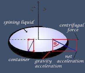
A rotating liquid surface takes the shape of a paraboloid under the constant pull of gravity and the centrifugal acceleration, which grows stronger with the distance from the central axis (E. Cappoci, 1850). The paraboloid shape occurs because a liquid surface always sets its local surface perpendicular to the net acceleration it experiences, which in this case becomes stronger and more inclined with distance from the central axis.
Consequently, a Liquid Mirror Telescope can be made by using a liquid mirror as the primary mirror and by putting a camera at the focus of the paraboloid.
Liquid mirror telescopes are Zenithal pointing telescopes: they can only see a small field of view around the Zenith (point along the local vertical direction). Pointing objects, as done when using classical technology telescopes, is no longer possible. Integrating images with LMTs is done using a new real-time imaging technique called Time Delayed Integration (TDI, see below).
Thanks to the Earth rotation, the telescope scans a strip of constant declination equal to the latitude of the location. Because a LMT observes the same region of the sky night after night, it is possible either to co-add the images taken on different nights in order to improve the limiting magnitude attainable, or to subtract images taken on different nights to make a variability study of the corresponding strip of sky. Consequently, a LMT is very well suited to perform photometric variability studies of the strip of sky it observes.
The primary mirror
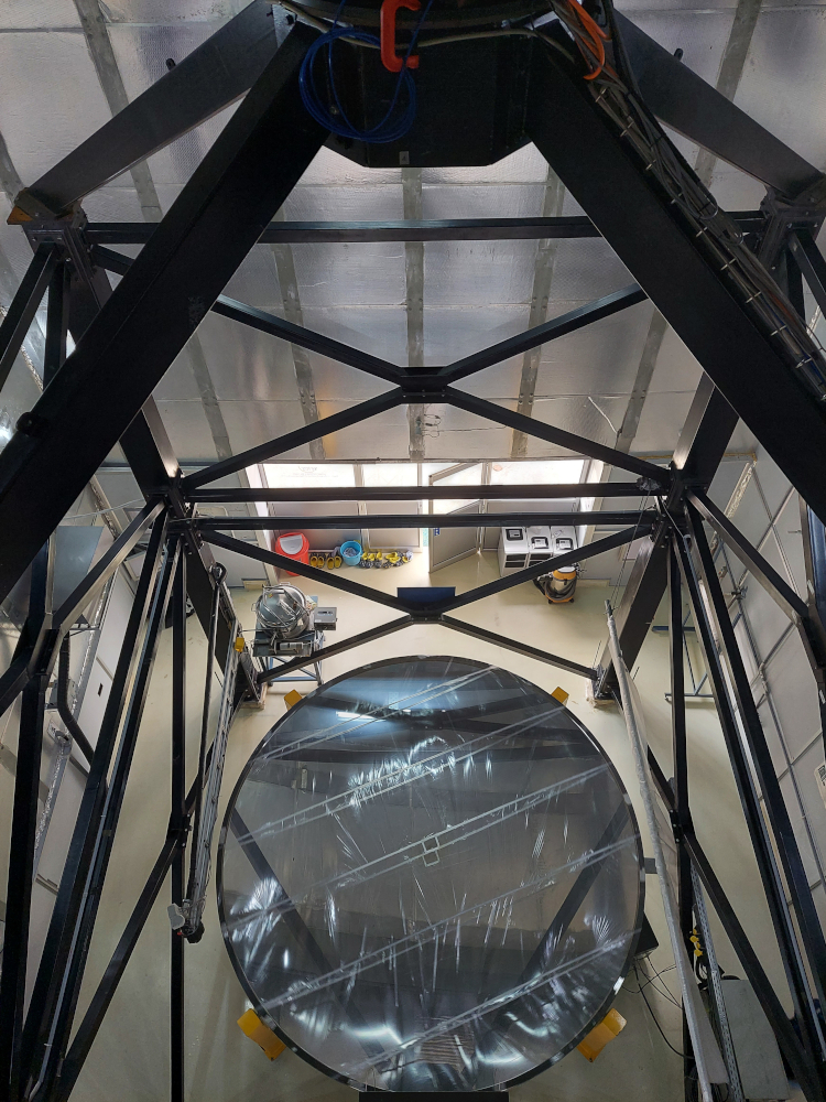
Mirror is covered with a thin film of liquid mercury that has a thickness of about 3.5 mm, which corresponds to a weight of 650 kg of mercury rotating around its vertical axis with a period of approximately 8 seconds to maintain its shape. Its shape is that of a paraboloid with a focal length of approximately 8 m. It is supported by a closed-cell foam core and carbon fiber-epoxy skin. The top surface was finished by applying two layers of polyurethane, formed by spincasting. The mirror was designed and built by the company Advanced Mechanical and Optical Systems (AMOS, Liège, Belgium). Before the telescope was transported to India in 2011, several technical difficulties were resolved thanks to critical experiments carried out by UBC and University of Liège astronomers. These included improving the rigidity of the mirror and its mechanical interface with the air bearing, spin casting, and checking the quality of the mercury surface.
at the left: Top view of the ILMT mirror surfaced with mercury and covered with thin assembled Mylar films, which prevent the formation of ripples on the surface of the mercury. A tube is attached to the aluminium beam, just to the left of the edge of the mirror, to pump the mercury to and from the mirror and the tank visible at the top left side of the mirror.
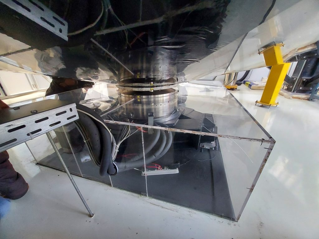
The air bearing and pneumatic systems
The mirror sits on a thin film of pressurized air to provide a low friction load-bearing interface between surfaces. This allows for incredibly smooth, vibration-free rotation, which is essential for maintaining the perfect optical surface and ensures smooth rotation with minimal friction. The ILMT uses an air-bearing (Kugler: model RT-600T) that is attached to a three-point mount for levelling. It can support a load of approximately 1000 kg. It is driven by a brushless DC motor integrated within the air bearing. The air bearing is enclosed in a Plexiglass box to maintain an ambient temperature of 20°C.
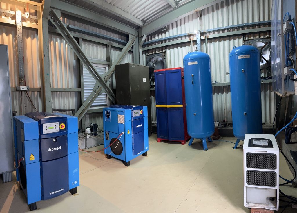
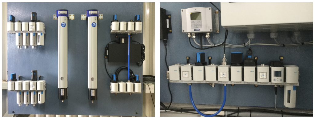
Compressors and tanks In order to ensure an uninterrupted supply of clean dry air to the air bearing, two independent pneumatic air systems were installed. These consist of two air compressors, two air tanks (see Fig. up). | Air filtration systems Double air filtration systems located in the compressor room (left). A separate equipment combines air from each system providing further filtration, pressure regulation and sensors (right). The latter equipment is located in the telescope control room. |
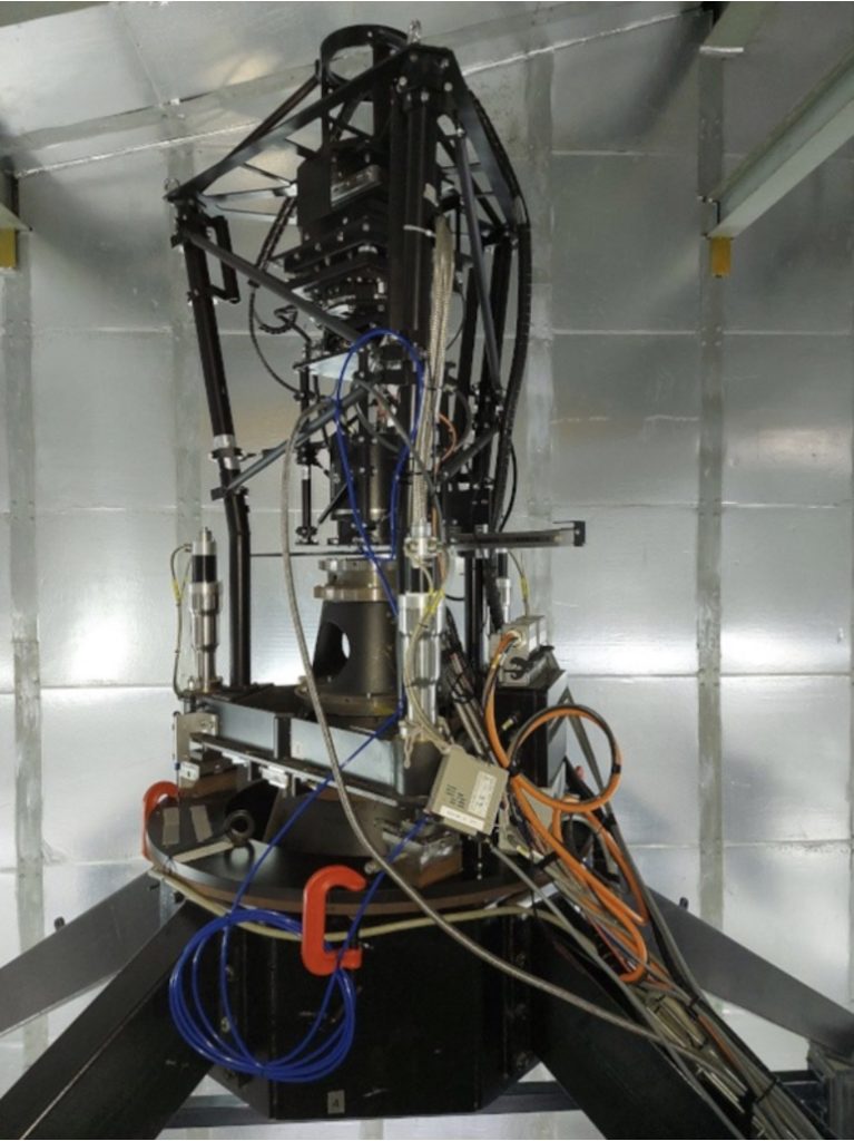
Telescope structure and top end
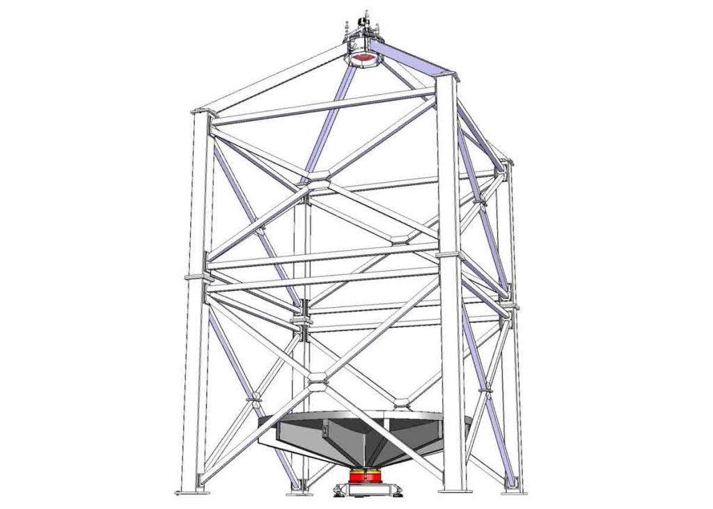

| Upper figure shows the four lower pillars, the lateral reinforcement bars, the four upper pillars and the telescope’s spider structure that holds the optical corrector and CCD camera. | At the top, a deployable platform is seen for access to the prime focus of the telescope. |
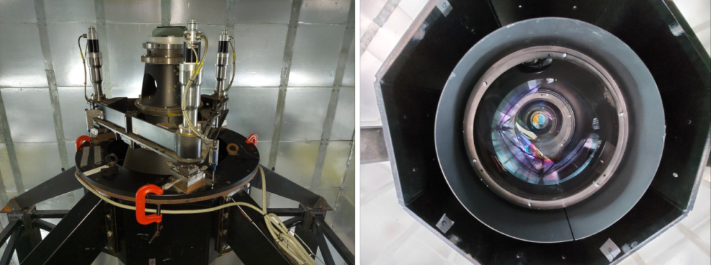
Optical Corrector :
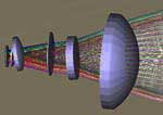
Due to the Earth’s rotation, the trajectories of stars in the focal plane of a liquid mirror telescope located at the latitude of +29°21’41.4″ correspond to hyperbolic trajectories . The ILMT is equiped with a five-element refractive optical corrector designed for TDI observations, correcting off-axis aberrations and compensating for distortion caused by the Earth’s rotation.
As the primary mirror is paraboloid, the off-axis imaging is distorted by several aberrations (mostly distortion, spherical and coma). In order to correct these and to increase as much as possible the field-of-view of the telescope, an optical corrector is inserted before the CCD camera. It does also remove the TDI distortion. Indeed, while using a classical corrector, the TDI technique degrades the images. This comes from the fact that the TDI technique moves the electrons along a straight line over the CCD at a constant speed while the stellar images move at different speeds along distinct curved trajectories. The deformation depends on the latitude of the observatory (it is zero at the equator and increases with latitude). Optical design shows that it is possible to eliminate these effects by introducing an adverse deformation of the field thanks to the designed TDI corrector. The final goal of the corrector is to sufficiently compensate the aberrations to permit the ILMT to be a seeing limited telescope imaging a field of 22.3′ by 22.3′.
CCD Camera and Filters:
A mechanical structure is located above the optical corrector (figure on the left). Designed by CSL (Centre Spatial de Liège, Belgium) and built by Socabelec (Jemeppe-sur-Sambre, Belgium), it holds the CCD camera and a filter tray that contains three broadband filters and a dark slide. It is equipped with mechanisms for adjusting the position of the CCD camera along three axes of translation in addition to rotation about the optical axis. Filter selection, rotation and axial position of the CCD camera are controlled remotely. A 4096×4096-pixel CCD camera is equipped with broadband filters (g′, r′, i′) matching the SDSS photometric system. The camera operates in TDI mode to track stars electronically.
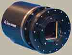
The ILMT is equipped with a CCD camera whose sensor is a 4096 by 4096 pixel matrix. Both the Liège University (IAGL; Special Research Funds, Large equipments) and the Royal Observatory of Belgium (ROB; LOTTO grant) have contributed to the purchase of the ILMT 4k x 4k CCD camera. As previously written, LMTs are not able to track celestial objects as conventional telescopes do. In the case of the ILMT, tracking is done electronically, by using the special CCD readout technique known as Time Delayed Integration (TDI). Taking an image with a CCD camera is usually done in two steps. First, the sensor pixel matrix is exposed to the light of the source which is imaged. During the exposure, photoelectrons are generated and stored in the pixels of the sensor. The number of photoelectrons generated in a pixel is proportional to the flux of light arriving in the pixels during the exposure. Secondly, the number of photoelectrons in each pixel is counted: this step is called the CCD readout. Classical read out of a CCD is done by successively drifting each column of the sensor pixel matrix to an electronic device, the register located just next to the sensor, which counts the number of photoelectrons in all the pixels of each column. In the TDI mode, the drift of the columns is slowed down. In the case of the ILMT, as a star goes through the field-of-view of the telescope, its image crosses the sensor. The drift of the columns is slowed down in such a way that photoelectrons generated by the star are drifted over the sensor at the same speed as the image of the star travels through the focal plane. Consequently, as soon as a star gets out of the field-of-view, the number of photoelectrons it has generated is counted. So TDI is a real time imaging technique. At each moment, the ILMT creates an image of the field of sky passing at the zenith.
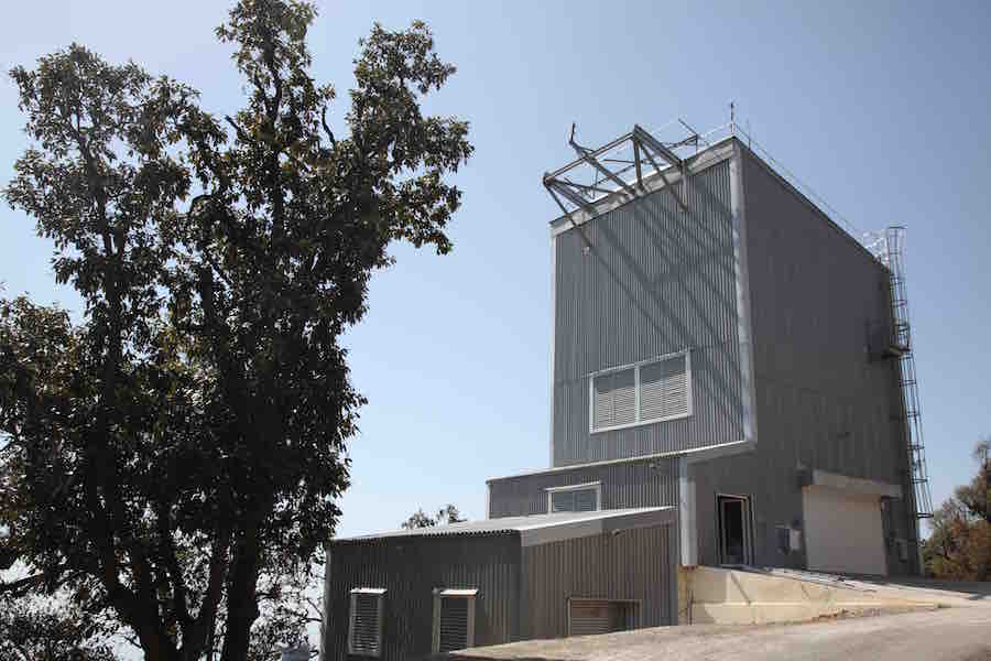
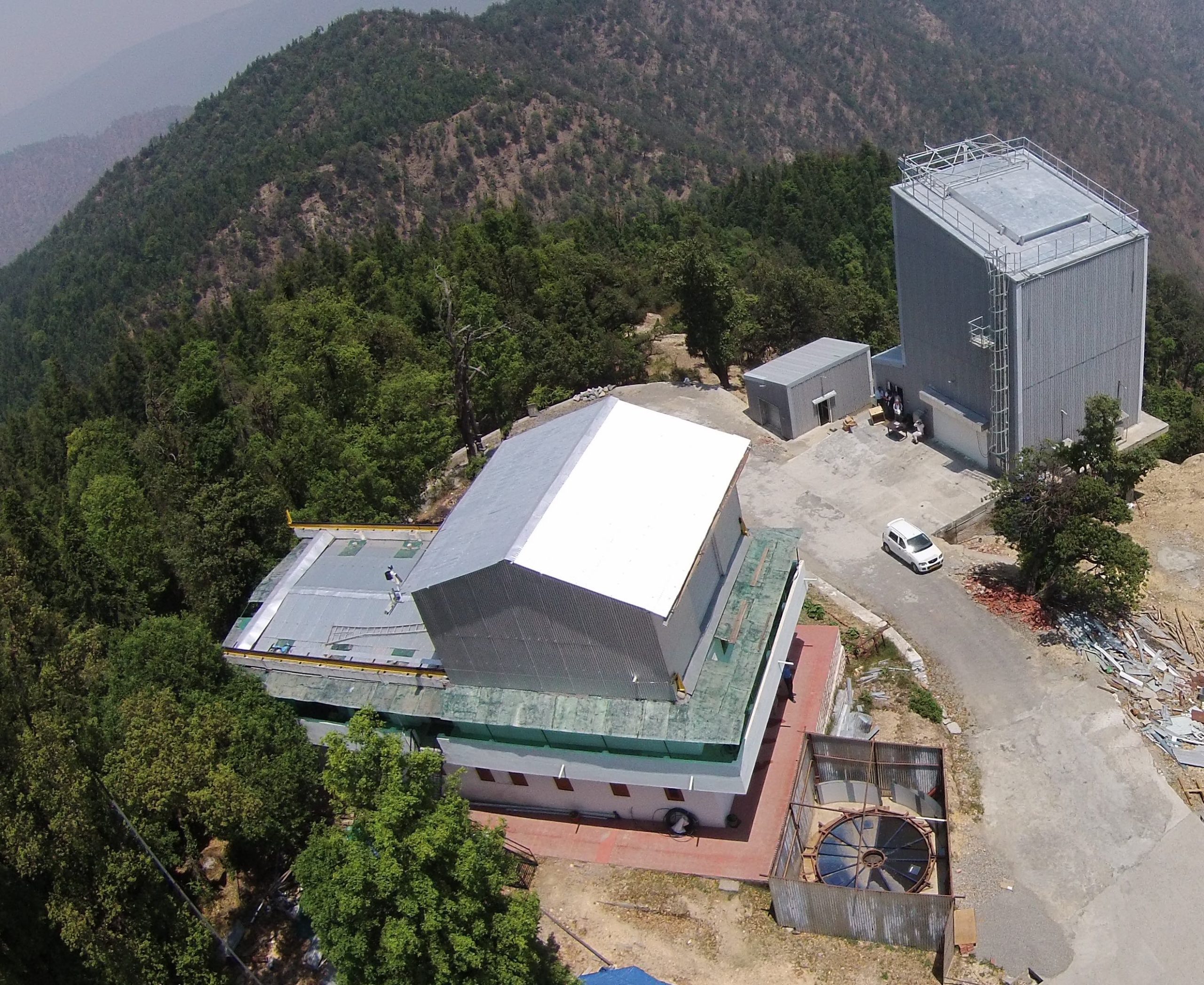
The telescope enclosure
A building with a retractable roof hatch, housing the telescope, control room, and compressor room. It is equipped with ventilation, air conditioning, and mercury safety measures.

The ILMT building is located opposite to the 1.3m DFOT building at Devasthal and consists of three parts: the compressor room, the control room and the telescope enclosure. The compressor room is a small building located far enough away from the telescope pier to avoid transmitting vibrations to the mirror. The AMOS telescope control unit, the Socabelec panel which controls the prime-focus interface, the local data server and the mercury monitors are installed in the control room. The control room is isolated from the telescope enclosure and sealed to prevent any leakage of mercury vapour into the room. The main enclosure employs a sliding roof shutter that opens to permit observations.

The building is equipped with four exhaust fans for ventilation and is air-conditioned during the day. Two cameras in the telescope enclosure allow observers in the control room to see the mirror. An all-sky camera and weather station (Vaisala 536 series) are installed on the roof of the telescope enclosure to monitor the sky at night and the weather.